Other Methods
17mm / 14mm in diffuser panels, installed between joists
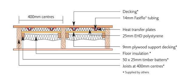
Insulation: Part E of the Building Regulations requires a minimum of 100mm mineral wool insulation to be placed in the joist void in separating floors for acoustic reasons. For ground floors or floors over unheated areas, at least 150mm of mineral wool should be fitted below the panels. Check with the architect whether Part L of the Building Regulations requires thicker insulation to be used.
Floor structure: Laminate floors thicker than 20mm may be laid on up to 3mm thick non-felt underlay directly onto the underfloor heating. Areas to be tiled can be covered by a plywood deck instead of chipboard. A quality two-part adhesive may then be used for fixing the tiles. For other areas 18 – 22mm chipboard deck may be used. The overall thickness of the deck should not exceed 30mm unless this has been agreed with a Nu-Heat Design Engineer.
1. Notching details are included with the system design CAD and should be carried out in accordance with current building regulations.
2. Push mineral wool into the gap between each joist, (see notes on insulation on previous page).

3. Fit a batten along the side of each joist. Screw a 9mm plywood support layer on top of it. The remaining gap should be 25mm to allow for the height of the panels.
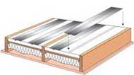
4. Place the polystyrene panels and diffuser plates on top of the support layer.

5. Fit the 14mm Fastflo tubing as in the instructions on the following pages.
6. Pressure test the system as in Section 2.2 of the Installation Manual.

7. Fit the floor deck as described on the previous page.
Notes: To avoid injury always wear gloves when handling plates. Care should be taken to ensure plates make good contact with the floor deck.
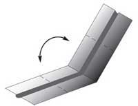
1. To snap plates to size, carefully bend the plate up along the score line and flex up and down until it breaks free.
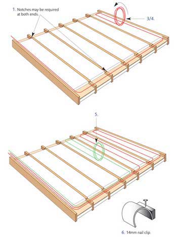
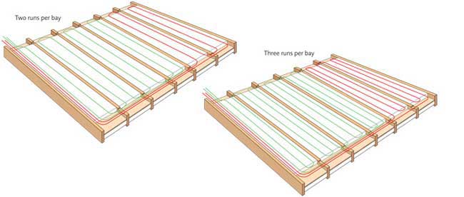
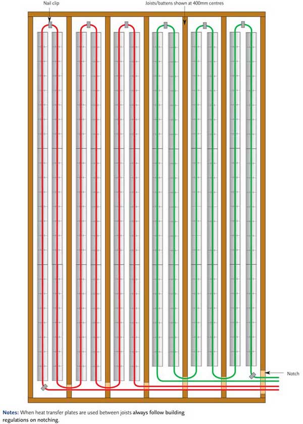
1. Ensure notches or spaces are left at the ends of batten runs to allow tube to pass. Note:Where 3 pipe runs per bay are shown on the CAD, notches will be required at both ends.
2. Check the number and length of floor heating coils needed for the room on the system plans.
3. Connect one end of the tube into the flow manifold as shown in the manual. Start unrolling the tube pushing it into the diffuser plates as you go. The tube will automatically be held at the correct spacing. Do not kink the tube.
4. Follow the CAD layout and then take the tube back to the manifold. Do not trim any excess or connect to the return manifold at this stage.
5. The second coil can now be laid in exactly the same way.
6. Individual 14mm clips can also be used to secure tube on turns or wherever necessary.
7. Now simply continue working across the floor and back to the manifold making sure the floor is fully and evenly covered with tube.
8. When the correct number and lengths of tube are laid in the floor, trim excess coil length and connect to the return manifold as described in the manual.
9. Pressure test the system as described in Section 2.2 of the Installation Manual.
